Planar Transformers
Low-profile, high-frequency planar transformers with PCB or lead-frame windings — custom-designed to your turns ratio, isolation, and footprint.
About this series
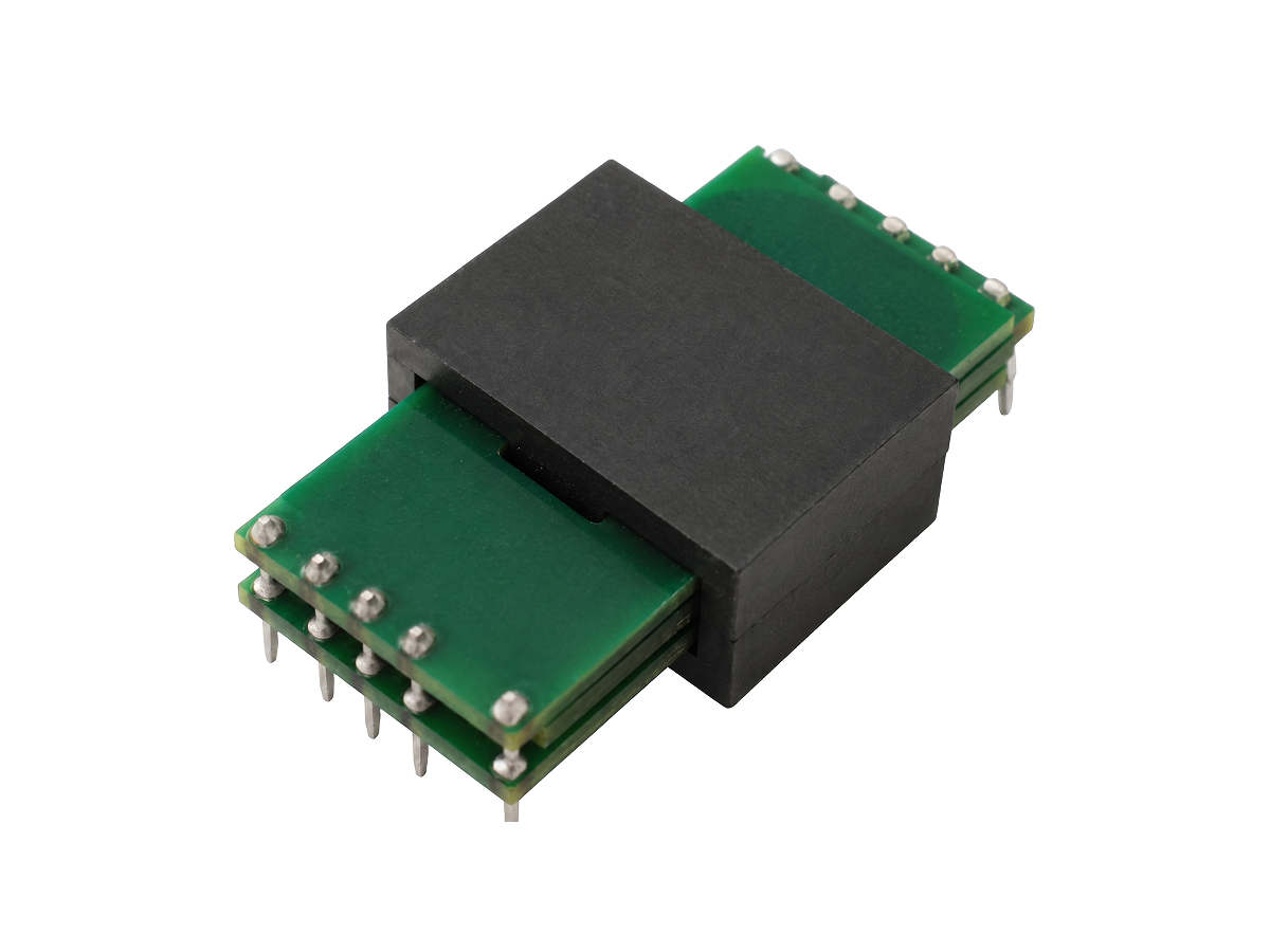
Planar transformers replace round magnet wire with flat copper windings — etched traces on a multi-layer PCB or stamped lead frames — clamped between two halves of a low-profile ferrite core. The thin, repeatable copper layers stay within the high-frequency skin depth and can be precisely interleaved to cut proximity-effect loss, delivering high power density, a low profile, and strong thermal performance for switching converters running from roughly 100 kHz to several MHz. febetek designs planar transformers to customer specification — turns ratio, isolation class, core geometry, and footprint — built under a UL-recognized insulation system.
Features
- PCB-winding or lead-frame construction for a low-profile, high-power-density build
- Optimized for high-frequency operation (≈100 kHz to several MHz)
- Interleaved windings to reduce proximity-effect loss and tighten coupling
- Repeatable leakage inductance and parasitics for predictable EMI performance
- UL-recognized insulation system; custom turns ratio, isolation, and footprint on request
Common Applications
- LLC / CLLC resonant converters
- EV on-board chargers (OBC) and DC-DC converters
- High-density telecom and server power supplies
- Industrial SMPS and high-frequency power conversion
- Renewable energy converters (solar / energy storage)
Read the design guide
What Is a Planar Transformer? Definition, Construction, and How It WorksFrequently Asked Questions
- A planar transformer is a transformer whose primary and secondary windings are flat copper layers — etched on a multi-layer PCB or stamped as lead frames — clamped between two halves of a low-profile ferrite core. It is designed for switching frequencies of roughly 100 kHz to several MHz, where flat copper and interleaved layers outperform round magnet wire.
- A conventional transformer uses round magnet wire on a bobbin; a planar transformer uses flat PCB copper or lead frames. Planar designs are typically lighter and lower in height with more repeatable unit-to-unit parasitics, at the cost of higher PCB tooling investment and a lower practical turns count.
- Most planar designs operate between roughly 50 kHz and 2 MHz. Below about 50 kHz the high-frequency advantage shrinks and wire-wound is more economical; near the top end, inter-winding capacitance becomes the limiting factor.
- The main trade-offs are a limited turns ratio (wide PCB traces constrain turns count), higher inter-winding capacitance from large overlapping layers, and PCB tooling cost that favors higher production volumes. Below the high-frequency inflection point they offer little benefit over wire-wound.
- Yes. EV on-board chargers and DC-DC converters commonly use LLC / CLLC resonant topologies running at 100 kHz–500 kHz, where planar transformers' low profile, thermal performance, and repeatability are well matched. They are also widely used in telecom, server, and industrial high-frequency power supplies.
- The full series complies with RoHS and REACH. A Conflict Minerals declaration is available on request (please specify in your RFQ). Detailed environmental declarations are available from our sales team.
- MOQ and lead time vary by part number and order size. Samples have lower MOQ; production volume is by mutual agreement. Indicate your estimated quantity in the RFQ form for a specific quote and lead time.
- Submit through the Contact page RFQ form or email [email protected]. Our team supports Traditional Chinese, English, and Japanese with response within 1 business day.